I recently built a GoPiGo robot car from Dexter Industries. The car is a complete robot platform built around the popular Raspberry Pi single board computer. Once you build the car, you can log in to the robot over ssh or even a desktop environment via VNC. Either way, the robot’s behavior is fully programmable using a variety of languages. The most commonly used library is for Python, and that’s what I am using.
If you opt for the GoPiGo starter kit, you get the robot car, the Raspberry Pi, a servo, an ultrasonic sound sensor for measuring distances, and a handful of other useful items like a wifi dongle and software preloaded on an SD card. If you’re just getting started, this is the package I recommend. It will cost you just under $200.
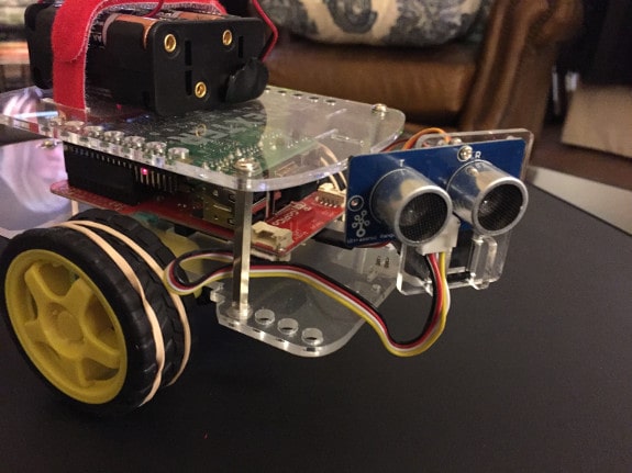
When I built my car, I mounted the distance sensor on the servo at the front of the car. The servo mount gives me the ability to rotate the sensor on the front through nearly 180 degrees, to scan the horizon for obstacles without moving the car.
The distance sensor sends out a pulse of 40KHz sound, and waits for the return echo. Using the time elapsed, it returns a distance between the sensor and an obstacle.
My Room Mapping Project
With the car up and running, my first project was to use the mobility of the car along with the ultrasonic sound sensor to map the environment. By driving to a spot and then rotating the sensor I would record the distances to objects in the room. Then I would reposition the car and do it again, slowly acquiring a virtual map of the room.
A Simple Approach
The easy approach is to simply rotate the servo, scan for distances, then rotate the car and do it again. It will take at least 3 scans to make a starting 360 degree scan, because my mounting of the servo reduced its rotation range from 180 degrees to 155 instead. (The mount runs into a plastic plate before it gets all the way to the right maximum.)
I quickly realized there are some inaccuracies with this method. There is no need to introduce errors when they are avoidable, so let’s see if we can do better.
So, what is the issue? The servo has an arm that extends the sensor out in front of the car, and as the servo rotates, the physical location of the sensor can be closer or further from the obstacle whose distance it is measuring. What we really want is the distance from a fixed point on the car, as if the sensor were statically mounted there.
My Improved Approach
The best place from which to measure distances is the center of rotation between the wheels of the car. That way, when we rotate in place using the wheel motors, the next scan will generate data from the same origin point.
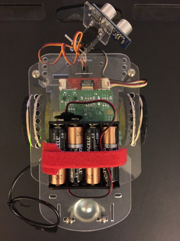
Here are some images that will help me explain. Here is a top view of the car:
Important Points for our Calculations
Here is a similar shot, labeling important points in red:
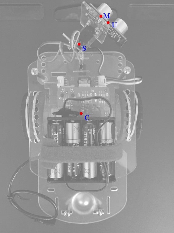
The labeled points are:
- C: The Center of rotation, mid-point between the wheels
- S: The center of the Servo motor. The servo rotates from here.
- M: The Mounting plate, where the servo arm connects to the distance sensor mount.
- U: The Ultrasonic distance sensor’s mid point, from which distances are measured.
- O: Not pictured yet, this will be the location of an Obstacle we are detecting.
Let’s say we rotate the servo to a particular direction, and receive data indicating there is an obstacle a certain distance from the sensor. At that servo angle, there is an obstacle at that distance from point U. Our goal is to translate this to a direction and distance from point C instead.
It’s worth noting that when the servo motor is in its default home position, it points straight ahead. And that setting is identified as “90 degrees”. For compatibility, I will maintain that convention and identify “straight ahead” as a direction of 90 degrees.
You do remember some of that trigonometry you learned in high school, right? We have a lot of trig calculations to make along the way. Don’t worry. I’ll explain them as I go.
The Basic Diagram for the Problem
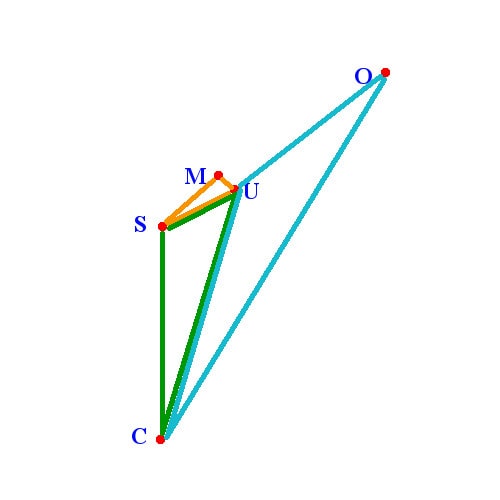
These are the same points labeled in the photo, and I have added three colored triangles that are the key to all the calculations that follow.
A few important points
Note that the sensor direction line UO (ultrasonic sensor to obstacle) is parallel with line SM (servo to mount), because the angles at both M and U are right angles.
Also remember that a direction of “90 degrees” means that line SM would be straight ahead (vertical in our diagram). My example diagram shows a servo setting of approximately 45 degrees.
Whenever we make a measurement, we will generate two pieces of information: the servo angle, and the distance we get back from the sensor. In our diagram, that distance is the length of line UO.
S – M – U: The “Easy” Orange Triangle
I will start with the easy part, a triangle whose vertices are static fixed points. That is the orange triangle in the diagram, with points at S, M, and U. The line connecting S and M is the servo arm, which is connected to the servo motor at point S, and connected to the mounting plate at point M. I will use the simple convention of naming each line segment by its end points. So the servo arm is line SM.
Similarly, the line MU is merely the distance from the mounting point to where the sensor’s center of detection lies.
Because SM and MU are constant length, and the orange angle M is a right angle, we can easily calculate the length of SU and the angle at S, which we will need later:
Using the Pythagorean formula,
\[SU^2 = SM^2 + MU^2\]
or
\[SU = \sqrt{SM^2 + MU^2}\]
To get the orange angle at S, remember that in a right triangle,
\[tan = {opposite \over adjacent}\]
so
\[Angle\ S\_orange = arctan{MU \over SM}\]
I measured the key distances on my car, and here is the first bit of Python.
import math

# Hardcoded measurements from GoPiGo (measure yours!)
# Distances in centimeters
CS = 8.57   # From center of car to servo
SM = 3.18   # From servo to mount
MU = 1.11   # From mount to ultrasonic sensor

# Incoming parameters
servo_angle = direction
UO = distance  # distance measured by the sensor = line UO

SU = math.sqrt(SM**2 + MU**2)
S_orange = math.degrees(math.atan(MU / SM))
C – S – U: The Green Triangle
We need information about the length and direction of line CU, so we can get that by solving the green triangle. We have the lengths of SU and CS already. Let’s find the green angle at S. It’s just 90 degrees plus the servo angle minus the orange angle at S.
\[S\_green = 90\ +\ servo\_angle\ -\ S\_orange\]We need to be careful here. Once the servo rotates much beyond 90 degrees, our value for the angle S_green will exceed 180 degrees. What that really means is that the green triangle has flipped to the other side of the diagram. Actually, this means that the green triangle has flipped to the other side of the line CS. (You’ll see why I make the distinction when we get to the same issue with the blue triangle!)
When that happens, I set C_green to 360 – C_green and set a flag “green_flipped”. We will use that flag later to handle these directions correctly.
With two sides and an angle, we calculate the length of line CU using the law of cosines:
\[c^2 = a^2 + b^2 – 2ab(cos(c))\]
In this case, it is:
\[CU^2 = CS^2 + SU^2 – 2\ CS\ SU\ cos(S\_green))\]
and therefore:
\[CU = \sqrt{CS^2 + SU^2 – 2\ CS\ SU\ cos(S\_green)}\]
We also need the angle C_green. We can use the law of sines:
\[\frac{sin(C\_green)}{SU} = \frac{sin(S\_green)}{CU}\]
\[C\_green = arcsin(\frac{SU * sin(S\_green)}{CU})\]
In Python:
# If point U is left of the line CS,
# then the green triangle is "flipped" across CS.
green_flipped = False
S_green = 90 + servo_angle - S_orange
if (S_green > 180.0):
        S_green = 360.0 - S_green
        green_flipped = True

S_green_rad = math.radians(S_green)

CU = math.sqrt(CS**2 + SU**2 - 2*CS*SU*math.cos(S_green_rad))
C_green_rad = math.asin((SU * math.sin(S_green_rad))/CU)
C_green = math.degrees(C_green_rad)
C – U – O: The Blue Triangle
One last triangle, and then we can get to our real target. For the blue triangle, we already know the lengths of UC and CU. Now we need the blue angle at U.
This may be the trickiest part. If you study the diagram, perhaps you can see the logic and follow along:
Angle U_blue is 90 degrees plus a couple of other angles we can find in the diagram. If you imagine a vertical line through point U (parallel to CS), the portion of angle U_blue which is left of the vertical line must be equal to the angle C_green.
In a similar way, a horizontal line through point U would leave an angle above the line which must be equal to the angle created where the horizontal line intersects SM. (Remember that UO is parallel to SM.) Fortunately, that angle is just servo_angle.
Put all that together:
\[U\_blue = 90 + servo\_angle + C\_green\]
Actually, that’s not quite right. If the green triangle is flipped, we must subtract servo_angle instead of add it. (Figuring that out took me a while!)
Either way, this calculation can exceed 180 degrees. This happens when the point O is to the left of line CU. Like before, we’ll use a flag “blue_flipped” to remember this, and correct the U_blue angle before continuing.
Now we can solve for our real interest, the length of line CO, which is the distance from the center of the car to our obstacle. We use the law of cosines again:
\[distance = CO = \sqrt{CU^2 + UO^2 – 2\ CU\ UO\ cos(U\_blue)}\]
We also need to find C_blue, so it’s back to the law of sines:
\[C\_blue = arcsin(\frac{UO * sin(U\_blue)}{CO})\]
In Python:
blue_flipped = False

U_blue = 90 + servo_angle

if (green_flipped):
    U_blue -= C_green
else:
    U_blue += C_green

if (U_blue > 180.0):
       # If point O is left of the line CU,
       # then the blue triangle is "flipped" across CU.
       U_blue = 360.0 - U_blue
       blue_flipped = True

U_blue_rad = math.radians(U_blue)

CO = math.sqrt(CU**2 + UO**2 - 2*CU*UO*math.cos(U_blue_rad))
C_blue_rad = math.asin((UO * math.sin(U_blue_rad))/CO)
C_blue = math.degrees(C_blue_rad)
Finally, the answers we’re looking for!
We have rounded third base, and are headed for home plate. We already have the distance of the obstacle from point C in line CO. Now we need to determine the direction of line CO.
A look at the diagram shows we need to add angles C_green and C_blue, and then translate back to the “90 degree is straight ahead” convention. But we also need to account for the times when the green or blue triangles are flipped.
I start with a direction of 90 degrees and then add or subtract the green and blue angles at C depending on the triangle direction:
The last bit of Python code:
distance = CO
direction = 90

if green_flipped:
    direction += C_green
else:
    direction -= C_green

if blue_flipped:
    direction += C_blue
else:
    direction -= C_blue
Wrapping up
It may be only a couple dozen lines of Python code, but it took a lot of figuring to get us there!
For our example servo_angle pointing to the right at 45 degrees, if the sensor finds an obstacle at 20 cm, these calculations yield a result showing that the obstacle is 29.66 cm away from the center of the car, in the direction of 54.61 degrees.
To show how this would differ from the simple approach, what happens if we rotate the servo to point to the left by that 45 degree angle instead? That’s a servo setting of 135 degrees. An obstacle at the same 20 cm from the sensor is actually 28.70 cm away from the center of the car, at a direction of 130.60 degrees.
For objects that are very close to the car, these differences can be quite large.
Using these normalized numbers will make our task a lot easier once we start rotating the car and taking multiple measurements. If I get a chance to write up the next step in my project, you will see some of the reasons why I considered this important.
If you want to grab the entire source code, I have it available as a Python function here:
dir_and_dist_from_center.py
Feel free to use it in your own projects. I recommend making the actual base measurements on your particular car before you begin, and edit the values near the top of the function.
Enjoy!
2 replies on “Better Data with the GoPiGo Robot Car’s Distance Sensor”
I used my tape measure and it took me 2 minutes to map out a room.
Actually, I’m very impressed. So, what exactly is this mapping device for????
Upon measuring physical distances compared to the sensor reported distances, I found that my sensor was consistently returning a distance inflated by a factor of 1.3.
I attribute this to an issue with the pulseIn command in the firmware, but I can’t be sure. Regardless, I found a very effective translation:
Actual distance = (Reported distance + 2.75) / 1.30
I assume the 2.75 cm adjustment has to do with the devices origin point.
In my case, the adjusted values have a maximum error of about half a centimeter.
I recommend that you test your own sensor to see what adjustments may be necessary.